Above we can see the latest design of a industrial manipulator in this thesis. The picture shows the first two rotational joints. This is a rigid type of manipulator with modular parts. Consider the design as a construction set which allow us to assembly the parts in different ways for producing manipulators for different purposes.
Above we see the same design, only sliced for showing the inside. Motors, sensors and circuitboards are assemblied inside each joint in the industrial robot arm. Notice how the wires will lay up inside this model. The wires will not be twisted as the robot arm rotates each joint.
As an example of a "pick and place" robot based on the latest design above, we here see a suggestions of construction with the modular parts. End effector, i. e. a gripper or a tool, have the opportunity to be mounted on top of the robot arm.
Above we see a earlier design which the latest design is mostly based on. Nearly the same modular parts.

The model is sliced for showing the inside. The biggest difference between this design and latest design is that this design has supporting parts assemblied between each modular part.
Above we see one of the earliest modular-based parts drawed in this thesis. Here in the process of mounting all the parts together in an assembly. The later designs is based on this and the design below.
The design above is ment as the bottom part joint in a rigid robot arm and is based on the earliest designs in this thesis.
The bottom joint is showed above with gears for rotating the next join, which will be mounted on top of this part. Space for the gear is not available in this model.

Above we see the same model but sliced for showing the mounting of the motor and sensor on the part.
The design in the picture above is also one of the earliest design of the rigid robot arm. Here shown in assembly with all part mounted together. The assembly is ment as bottom-joint in the robot arm. The bigger gear in the middle is driven by a motor to the left and an optical encoder (a type of sensor) is reading the mechanical degrees when the middle gear rotates. The optical encoder is mounted with a smaller gear to the right in this picture.
Same model as above this picture.
Above we see the actual assemblied part from the design in the two pictures above this picture. The assembly was printet in a stratasys 3D printer on the robotics lab, department of informatics, University of Oslo. This product was tested with motors and sensors controlled by arduino circuitboard and works nearly perfect. The drawback with this was the motor, which was too small, weak and inaccurate. The latest designs have bigger motors which is more accurate and stronger, but the costs of producing bigger parts is more expensive.
A closer picture of the part which is containing the motor in the assembly.
Drawings of the design shown above.
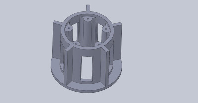
This is the main part of the bottom joint, shown as a drawing.
This part is for the sensor and is mounted on the main part on one of the sides.
Above we se what we could call a "test bench". This is for the purpose of testing the position accuracy on the motor. The optical sensor is mounted on and axle with the motor for reading exactly how much the motor rotates. The test bench was also drawed in SolidWorks and printed on the 3D printer.


